- Published on
APRS & AX.25 Demystified: Full Packet Generation and Frame Encoding
Overview
Introduction
Documentation for APRS and AX.25 is very terse. Implementing simple projects can be incredibly difficult if you are not familiar will every little detail of each level. A full implementation requires a bit of knowledge in APRS, AX.25/HDLC, and AFSK. I'm hoping that this example will help someone fill in the final gaps for some while attempting to implement APRS/AX.25 UI frames.
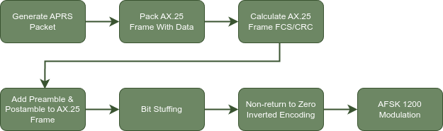
This article series will take a look at a single APRS packet. We'll encode the APRS data and then we'll pack it into an AX.25 UI frame.
APRS Packet Generation
The APRS portion is incredibly straight forward, it's all printable ASCII.
The specific type of APRS packet that will be used here is the compressed location packet. There any many other types of APRS packets, but most of the information here still applies. To find out more about other packet options check out the full APRS specification document.
Overall, an APRS packet will contain the following information:
| Source Call Sign & SSID |
| Destination Call Sign & SSID |
| Digipeater Path (optional) |
| Information Field |
APRS Address Fields
First, we need a few bits of information to generate a generic APRS packet.
Source Call Sign & SSID
- The source call sign is your call sign. For example, my call sign,
KD9GDC. In this guide we'll useNOCALL. - The SSID can be a number from 0 to 15, checkout the APRS 1.1 SSID Addendum for more information about what SSID to choose.
- For the SSID, we'll use the generic option of
1.(APRS SSID Recommendations, 2012)
Destination Call Sign & SSID
- The destination call sign is a bit more complex, For now, we'll just go with
APRS1 with an SSID of0.
Digipeater Path (optional)
- For the digipeater path, we'll go with
WIDE1-1. - It's not worth diving into digipeater paths here, checkout this great guide from aprs.fi, posted by Hessu.
APRS Information Field
For the compressed location packet, we need some more information:
- Desired Map Symbol:
Balloon - Time in Zulu:
9:23:45 - Latitude, Longitude:
40.3392208,-73.6247931 - Speed:
42 Knots - Bearing:
176 Degrees - Altitude:
88132 Feet - Comment:
Hello World!
The following table covers the format of the information field. We'll generate this piece by piece.

Data Type Identifier
Every APRS packet's information field starts with a APRS Data Type Identifier. This will be @ as we want to encode the position with a timestamp and APRS message.(APRS 1.0 Specification, 2000, p. 17)
@
Zulu Time
Next, the time needs to be formatted. This fairly simple as the format is HHMMSSz. So 9:23:45 turns into 092345z.(APRS 1.0 Specification, 2000, p. 22)
@092345z
Symbol Table Identifier
This will either be / or \ referring to the primary or alternate symbol table respectively.(APRS Symbol Table 1.1, 2015) The balloon symbol is /O, so this will be /.
Checkout www.aprs.org/symbols.html for the full symbol table.
@092345z/
Compressed Latitude and Longitude
Compressed location data is base 91 encoded, allowing it to fit within 8 ASCII characters.
It's calculated in the following way:
lat_base10 = 380926 x (90 - latitude)
lon_base10 = 190463 x (180 + longitude)
It's then converted into a base 91 number. Each base 91 symbol must be offset by the value 33 so that it will be printable ascii.(APRS 1.0 Specification, 2000, p. 38)
Example:
Latitude:
380926 * (90 - 40.3392208) = 18917081

18917081 / 91^3 = 25, remainder 77806
77806 / 91^2 = 9, remainder 3277
3277 / 91^1 = 36, remainder 1

25 + 33 = :
9 + 33 = *
36 + 33 = E
1 + 33 = "

Final :*E"

Longitude:
190463 * (180 + -73.6247931) = 20260541

20260541 / 91^3 = 26, remainder 667695
667695 / 91^2 = 80, remainder 5215
5215 / 91^1 = 57, remainder 28

26 + 33 = ;
80 + 33 = q
57 + 33 = Z
28 + 33 = =

Final ;qZ=
Here's a semi-readable Python script to encode the position: aprs_lat_lon_encode.py
Now that we have our compressed latitude and longitude, which are both 4 characters wide, we can put this into our packet.
@092345z/:*E";qZ=
Symbol Code
Going back to the symbol that we chose earlier, /O, we now need to add the O.
@092345z/:*E";qZ=O
Course & Speed
The next 2 bytes contain the course and speed, 1 character for each.2
Course: (heading / 4) + 33
Speed: log(knots + 1, 1.08) + 33
course:
176 / 4 = 44
44 + 33 = 77
77 = 'M'

speed:
log(42 + 1, 1.08) + 33 = 82
82 = 'R'
The information field now looks like this:
@092345z/:*E";qZ=OMR
Compression Type
The next byte is the compression type byte.(APRS 1.0 Specification, 2000, p. 39)
It's worth detailing here, but '0b00100010', or will be used.
67 = C
@092345z/:*E";qZ=OMRC
The Comment Field
The comment field has a maximum size of 40 characters. It can contain clear-text comments, along with some extra data. In this example we will stick with altitude data and a clear-text note.
Altitude in the Comment Field
The altitude is not compressed, and also not part of the main location data, so it can be omitted. It is located in the comment field. The altitude (in feet), is encoded as /A=aaaaaa.(APRS 1.0 Specification, 2000, p. 26)
With the altitude being 88132, the information field now looks like this:
@092345z/:*E";qZ=OMRC/A=088132
Clear-Text Message in the Comment Field
We already have /A=088132 in the comment field so we only have 31 characters remaining. The comment can contain any printable ASCII.(APRS 1.0 Specification, 2000, p. 20)
With the comment appended, we have:
@092345z/:*E";qZ=OMRC/A=088132Hello World!
The Complete APRS Packet
| Source Call Sign & SSID | NOCALL-1 |
| Destination Call Sign & SSID | APRS-0 |
| Digipeater Path (optional) | WIDE1-1 |
| Information Field | @092345z/:*E";qZ=OMRC/A=088132Hello World! |
This is the 'complete' APRS packet. It can now be passed on to generate the AX.25 frame.
APRS Text Format
When looking at raw APRS packets online you'll often see it in a specific format, all in one line. This packet would look like this(APRS 1.0 Specification, 2000, Chapter 17):
NOCALL-1>APRS,WIDE1-1:@092345z/:*E";qZ=OMRC/A=088132Hello World!
In this format, an SSID of 0 is omitted all together.
This concludes the APRS portion of the dive down the APRS stack!
AX.25 Frame Generation
APRS specifically uses only AX.25 UI frames(APRS 1.0 Specification, 2000, p. 12), which makes things nice and simple!

If you've looked at the official AX.25 specification you may become overwhelmed by all of the extra information not related to UI frames. Although intimidating, this specification document is very complete and incredibly helpful at times.
A Procedural Example of Generating an AX.25 Frame
We will generate this frame procedurally, byte by byte. This will be represented as a list of hexadecimal values.
| Flag | [] |
| Dst | [] |
| Src/Digi | [] |
| Control | [] |
| PID | [] |
| Info | [] |
| FCS | [] |
| Flag | [] |
Flag
The flag bytes at the beginning and end of the frame are easy, they're just the byte 0x73, this is at the start and end of all frames.
| Flag | [0x73] |
| Dst | [] |
| Src/Digi | [] |
| Src/Digi | [] |
| Control | [] |
| PID | [] |
| Info | [] |
| FCS | [] |
| Flag | [0x73] |
Addresses and SSIDs
This is where the textual representation of APRS packets starts to fall apart (but it's there for a reason!). In the textual representation the source address comes first, but in the actual AX.25 frame we can see that the destination actually comes first.
NOCALL-1>APRS,WIDE1-1
Address
Addresses are always 7 bytes long, the first 6 being the printable characters and the last being the SSID. If an address contains less than 6 characters, it is padded by trailing spaces. Each character of the address fields is ASCII, however they are shifted left by 1 bit. This is only done in the address field, not the information field.
SSID
Now for the 7th byte of the destination address, the SSID.
The SSID byte of the destination address is encoded as 111SSID0, where SSID contains the value of the SSID.
The SSID byte of the source address and digipeater addresses is encoded as 111SSIDL, where SSID is the same as above. L is set to 1 if it is the last address, otherwise it is set to 0.(Beech et al., 1998, Chapter 3.12.2)
Example
Starting with the destination address APRS, there is an SSID of -0 so it's omitted from the textual representation. To be clear, the character - from the textual packet does not appear in the AX.25 frame.
| Character | Value | Shifted |
|---|---|---|
| A | 0x41 | 0x82 |
| P | 0x50 | 0xa0 |
| R | 0x52 | 0xa4 |
| S | 0x53 | 0xa6 |
space | 0x20 | 0x40 |
space | 0x20 | 0x40 |
SSID 0, so 0b11100000 / 0xe0 Encoded Address: [0x82, 0xa0, 0xa4, 0xa6, 0x40, 0x40, 0xe0]
| Character | Value | Shifted |
|---|---|---|
| N | 0x4e | 0x9c |
| O | 0x4f | 0x9e |
| C | 0x43 | 0x86 |
| A | 0x41 | 0x82 |
| L | 0x4c | 0x98 |
| L | 0x4c | 0x98 |
SSID 1, and not the last address, so 0b11100010 / 0xe2 Encoded Address: [0x9c, 0x9e, 0x86, 0x82, 0x98, 0x98, 0xe2]
| Character | Value | Shifted |
|---|---|---|
| W | 0x57 | 0xae |
| I | 0x49 | 0x92 |
| D | 0x44 | 0x88 |
| E | 0x45 | 0x8a |
| 1 | 0x31 | 0x62 |
space | 0x20 | 0x40 |
SSID 1, and the last address, so 0b11100011 / 0xe3 Encoded Address: [0xae, 0x92, 0x88, 0x8a, 0x62, 0x40, 0xe3]
All the addresses are encoded, we can pack them into the frame.
| Flag | [0x73] |
| Dst | [0x82, 0xa0, 0xa4, 0xa6, 0x40, 0x40, 0xe0] |
| Src/Digi | [0x9c, 0x9e, 0x86, 0x82, 0x98, 0x98, 0xe2] |
| Src/Digi | [0xae, 0x92, 0x88, 0x8a, 0x62, 0x40, 0xe3] |
| Control | [] |
| PID | [] |
| Info | [] |
| FCS | [] |
| Flag | [0x73] |
Control & Protocol ID
The control field contains only 0x03 as this is a UI AX.25 frame. The Protocol ID field contains only 0xf0 as there is no layer 3 protocol used.(APRS 1.0 Specification, 2000, p. 12)
| Flag | [0x73] |
| Dst | [0x82, 0xa0, 0xa4, 0xa6, 0x40, 0x40, 0xe0] |
| Src/Digi | [0x9c, 0x9e, 0x86, 0x82, 0x98, 0x98, 0xe2] |
| Src/Digi | [0xae, 0x92, 0x88, 0x8a, 0x62, 0x40, 0xe3] |
| Control | [0x03] |
| PID | [0xf0] |
| Info | [] |
| FCS | [] |
| Flag | [0x73] |
Info
The info field will contain the raw data from the APRS info field. The bytes of this field are not left shifted like they are in the address field.
This means that we simply need to pack the values of @092345z/:*E";qZ=OMRC/A=088132Hello World!, which are all ASCII, into our frame.
| Flag | [0x73] |
| Dst | [0x82, 0xa0, 0xa4, 0xa6, 0x40, 0x40, 0xe0] |
| Src/Digi | [0x9c, 0x9e, 0x86, 0x82, 0x98, 0x98, 0xe2] |
| Src/Digi | [0xae, 0x92, 0x88, 0x8a, 0x62, 0x40, 0xe3] |
| Control | [0x03] |
| PID | [0xf0] |
| Info | [0x40, 0x30, 0x39, 0x32, 0x33, 0x34, 0x35, 0x7a, 0x2f, 0x3a, 0x2a, 0x45, 0x22, 0x3b, 0x71, 0x5a, 0x3d, 0x4f, 0x4d, 0x52, 0x43, 0x2f, 0x41, 0x3d, 0x30, 0x38, 0x38, 0x31, 0x33, 0x32, 0x48, 0x65, 0x6c, 0x6c, 0x6f, 0x20, 0x57, 0x6f, 0x72, 0x6c, 0x64, 0x21] |
| FCS | [] |
| Flag | [0x73] |
FCS
The AX.25 FCS is a CRC16 (ISO 3309) that starts at the first byte of the destination field and stops at the last byte of the information field.(Beech et al., 1998, Chapter 3.7) It's a standard CRC16 so you can find many implementations online. My personal favorite is this one by Andres Vahter.
Here is my modified version, but still based on the one made by Andres.
uint16_t calculateFcs(const std::vector<uint8_t> &input_data) {
  uint16_t crc = 0xFFFF;
  uint16_t crc16_table[] = {0x0000, 0x1081, 0x2102, 0x3183, 0x4204, 0x5285,
                            0x6306, 0x7387, 0x8408, 0x9489, 0xa50a, 0xb58b,
                            0xc60c, 0xd68d, 0xe70e, 0xf78f};

  size_t length = input_data.size();
  size_t iterator = 0;
  while (length--) {
    crc =
        (crc >> 4) ^ crc16_table[(crc & 0xf) ^ (input_data.at(iterator) & 0xf)];
    crc =
        (crc >> 4) ^ crc16_table[(crc & 0xf) ^ (input_data.at(iterator) >> 4)];
    iterator++;
  }

  return (~crc);
}
(Vahter, 2020)
Below is the full AX.25 frame.
| Flag | [0x73] |
| Dst | [0x82, 0xa0, 0xa4, 0xa6, 0x40, 0x40, 0xe0] |
| Src/Digi | [0x9c, 0x9e, 0x86, 0x82, 0x98, 0x98, 0xe2] |
| Src/Digi | [0xae, 0x92, 0x88, 0x8a, 0x62, 0x40, 0xe3] |
| Control | [0x03] |
| PID | [0xf0] |
| Info | [0x40, 0x30, 0x39, 0x32, 0x33, 0x34, 0x35, 0x7a, 0x2f, 0x3a, 0x2a, 0x45, 0x22, 0x3b, 0x71, 0x5a, 0x3d, 0x4f, 0x4d, 0x52, 0x43, 0x2f, 0x41, 0x3d, 0x30, 0x38, 0x38, 0x31, 0x33, 0x32, 0x48, 0x65, 0x6c, 0x6c, 0x6f, 0x20, 0x57, 0x6f, 0x72, 0x6c, 0x64, 0x21] |
| FCS | [0xa2, 0x48] |
| Flag | [0x73] |
Each of these lists just need to be put together, in this order, to form the full binary frame.
[0x73, 0x82, 0xa0, 0xa4, 0xa6, 0x40, 0x40, 0xe0, 0x9c, 0x9e, 0x86, 0x82, 0x98, 0x98, 0xe2, 0xae, 0x92, 0x88, 0x8a, 0x62, 0x40, 0xe3, 0x03, 0xf0, 0x40, 0x30, 0x39, 0x32, 0x33, 0x34, 0x35, 0x7a, 0x2f, 0x3a, 0x2a, 0x45, 0x22, 0x3b, 0x71, 0x5a, 0x3d, 0x4f, 0x4d, 0x52, 0x43, 0x2f, 0x41, 0x3d, 0x30, 0x38, 0x38, 0x31, 0x33, 0x32, 0x48, 0x65, 0x6c, 0x6c, 0x6f, 0x20, 0x57, 0x6f, 0x72, 0x6c, 0x64, 0x21, 0xa2, 0x48, 0x73]
AX.25 Frame Encoding
With a full AX.25 frame generated, there are only a few more steps to implement prior to AFSK modulation. I'll through a quick
Preamble Postamble - Using the Flag Byte
One thing worth mentioning now, prior to bit stuffing, is the preamble and postamble. In order for a receiving station to synchronize, often times adding a preamble helps. Along with this, I've found that with some software, adding a short postamble is helpful to decode the last few bits.
The flag byte is said to be standard for a preamble according to the AX.25 specification.(Beech et al., 1998, Chapter 3.11) However, the flag byte is the worst binary series if doing NRZ-I as it's the longest series of 1s.(Finnegan & Benson, 2014) This isn't defined in the APRS specification, but Kenneth Finnegan makes a solid argument for using 0s instead in his paper.
Also worth noting, only a single flag needs to be between two frames.(Beech et al., 1998, Chapter 3.1)
Bit Stuffing
Bit stuffing is done between the flag bytes, but not on the flag bytes themselves. To do bit stuffing, each bit of the frame needs to be looked at, in order from the first destination field bytes.
The bits of the FCS need to be taken in most significant bit first (Big-endian). The bits of all other fields need to be taken in least significant bit first (Little-endian).(Beech et al., 1998, Chapter 3.8)
Every time there are 5 consecutive 1s, an additional 0 needs to be inserted. You'll notice that the flag byte has 6 consecutive 1s, this is how you can recognize and synchronize the reception of an AX.25 frame. The flag bytes will be the only place where you will find more than 5 consecutive 1s.(Beech et al., 1998, Chapter 3.6)
After bit stuffing, the frame will look like this:
[0x7e, 0x41, 0x05, 0x25, 0x65, 0x02, 0x02, 0x07, 0x39, 0x79, 0x61, 0x41, 0x19, 0x19, 0x47, 0x75, 0x49, 0x11, 0x51, 0x46, 0x02, 0xc7, 0xc0, 0x07, 0x81, 0x06, 0x4e, 0x26, 0x66, 0x16, 0x56, 0x2f, 0x7a, 0x2e, 0x2a, 0x51, 0x22, 0x6e, 0x47, 0x2d, 0x5e, 0x79, 0x59, 0x25, 0x61, 0x7a, 0x41, 0x5e, 0x06, 0x0e, 0x0e, 0x46, 0x66, 0x26, 0x09, 0x53, 0x1b, 0x1b, 0x7b, 0x02, 0x75, 0x7b, 0x27, 0x1b, 0x13, 0x42, 0x22, 0x89, 0x3f, 0x3f]
Bell 202 AFSK
There is so little documentation related to the Bell 202 modem that is used in APRS. The closest thing to this is a paper titled "Clarifying the Amateur Bell 202 Modem" Finnegan & Benson (2014).
The Bell 202 modem operates at 1200 baud, using audio frequencies 1200hz and 2200hz.
NRZ-I : Non-return To Zero Inverted Encoding
NRZ-I will sometimes get packed into AX.25, but it's part of the Bell202 specification.
When encoding the bit stream one bit at a time, a 0 is encoded by switching from one frequency, to the other (1200hz -> 2200hz or 2200hz -> 1200hz). A 1 is encoded by not changing the frequency.
Implementation
The goal of this article is not to go in-depth into a Bell 202 modem. There are plenty of resources, much better than I could create, related to this topic.
By far, the most complete resource is the Not Black Magic - AFSK guide.
This would be a bit more of a challenge, but you can reference my implementation here.