- Published on
Understanding Phase Shift Keying (PSK) and Implementing PSK31 (BPSK & QPSK)
- Authors

- Name
- Joshua Jerred
Introduction
I've been playing around with Binary Phase Shift Keying (BPSK) and Quadrature Phase Shift Keying (QPSK) for a few weeks now. What I've found is that every implementation is either too complicated or only theoretical. I'm not an electronics, radio, signal processing, or math expert, but I still want to try to understand the basics of these technologies. After finishing my implementation of PSK125 I found that it was far easier than all of the other implementations. I took a few shortcuts but my code still generates filtered BPSK that is nearly identical to the ARRL spec.
This is more of a project log than a guide, but this may be a helpful resource for those who want to understand the fundamentals of BPSK/QPSK and how to implement it in software. To be clear, this is not a guide for people in academia who need to fully understand the math behind it. Even in my implementation, I did not fully use the complex (complex to my standards) formulas. I am an undergraduate, student in Computer Science and I am far from an expert in anything, this post is made for people like me.
Please keep this in mind and check other sources for the real science and math behind it, I will do my best to provide references. If you find any errors, please let me know. Many things in here may be gross oversimplifications but I rather you understand how relatively simple PSK is than to get overwhelmed by the scary formulas.
I'm fairly comfortable with calculus but I found that I did not need to apply it to this project. I'm also comfortable with linear algebra, but I decided to use a "slower" iterative approach to the math. There are some wonderful Python Numpy implementations of PSK that I found that I'd recommend taking a look at if you're into that sort of thing.
This implementation will specifically be suited for amateur radio use as I plan on using it for my weather balloon project. This means that the digital mode used must be well documented, so I'll be sticking to the ARRL's spec.
I'm going to be working with higher baud rates than PSK31 as I don't have any HF radios. PSK31 is really made for HF on SSB, but I plan on using it on VHF/UHF at high baud rates. I'm sure this has made some operators shudder, but I can hardly afford my DRA818 modules, let alone HF equipment.
Basic knowledge in the following topics is required to understand phase shift keying:
- Trigonometric functions (sine, cosine)
- Math up to pre-calculus (No derivatives or integrals needed here!)
- Phase, amplitude, and frequency of a wave
- ASCII/Data representation in binary
- AM/FM modulation
Waves: Amplitude, Frequency, and Phase
If you need to brush up on your wave knowledge, check out this article from geeks for geeks.
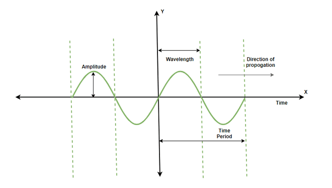
So, that's a wave. Let's put one on a graph. We'll start with a sine wave.
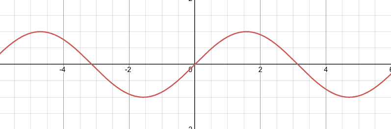
Go ahead and play around with this interactive sine wave on Desmos.
On the left side of the page you can see that the wave is defined as: sin(x*f + p) * a or sine(x * frequency + phase) * amplitude
Play around with the values of each slider and see how the wave changes.
Most important for us is the slider 'p' which controls the phase of the wave. Remember back in trig class when you learned about domain of the sine function? The domain of the sine function is [-pi, pi], or [-180, 180] degrees. Because the function is cyclic, we can also do [0, 2pi] or [0, 360].
The key concept here is that we can shift the wave left or right (change its phase) by adding an angle to the value of x. Congrats, you just made a phase-shifting wave!
Phase Shift Keying
Phase shift keying is a modulation technique that takes advantage of the 'phase' of a wave to encode data.
So what does modulation look like? First of all, we need something called a carrier wave. If we keep track of our carrier wave and its phase, we can modulate it. For example, if our carrier wave is sine(x), we can modulate it, or change its phase, by adding a phase shift to it.
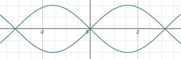
If we have sin(x), and another wave sin(x + p), we can compare the two waves and see that the second wave is shifted by p radians. Or, without abstract variables, we can look at what the difference between sin(x) and sin(x + 90°) looks like.
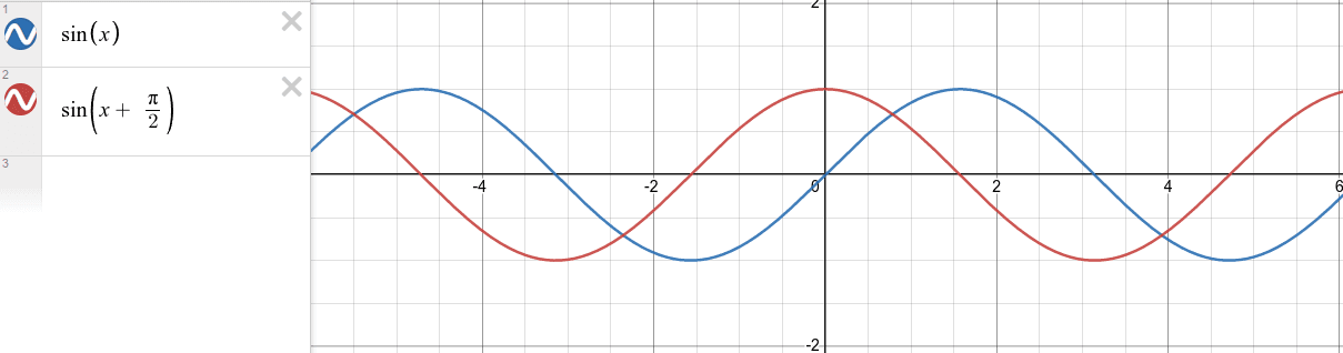
This is what it looks like for the sine wave to be "shifted by 90 degrees (pi/2)".
That's 90 degrees, but what about 180 degrees or 270 degrees (pi or 3pi/2 radians)?
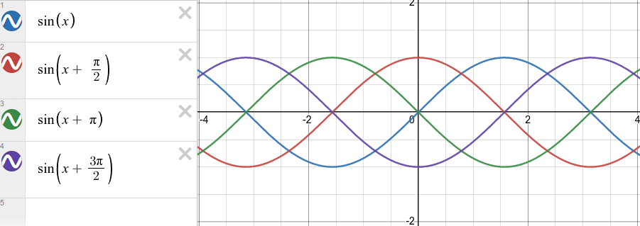
If you are comfortable with the fundamentals of trig functions I'm hoping that you can see that we have the same wave, but it's just being shifted by different values.
Let's simplify this a bit. Instead of four waves, let's go back to just two.
Binary Phase Shift Keying (BPSK)
BPSK is a form of PSK that uses two phases to encode data. The two phases are 0° and 180° (0 or pi).
We can use these two phases to encode data! For the sake of understanding, let's say that we can encode a 0 as 0° and a 1 as 180°.
With the graphs above you should consider the value of x to be the time. We can alternate between 0° and 180° to encode data.
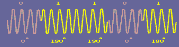 The image above is from Dr Moazzam Tiwana.
If you're looking for a more technical explanation, check out their article on BPSK.
I'm not going to go further into the concept of BPSK as other resources do a much better job of explaining the finer details. If you're looking to know more I'd look into the following topics:
- Differential BPSK vs. Non-Differential BPSK & CPSK
- Non-Return to Zero (NRZ) encoding
Quadrature Phase Shift Keying (QPSK)
QPSK is very similar to BPSK, but instead of using two phases, it uses four. The four phases are 0°, 90°, 180°, and 270° (0, pi/2, pi, 3pi/2).
With your intuition from BPSK, you can hopefully see that they are similar.
With the four distinct phases, we can encode two bits of data at once. An example of this would be to encode 00 as 0°, 01 as 90°, 10 as 180°, and 11 as 270°.
PSK31
PSK31 is a specific implementation of BPSK/QPSK that uses a 31.25 baud rate. This standard is used in amateur radio, generally in the HF bands. This is what I will focus on. I will use "PSK31" as a blanket term to refer to the amateur radio standard. Under this standard, we have both BPSK and QPSK at baud rates of 31.25, 62.5, 125, 250, and 500 baud. Being that the FCC requires any digital modes to be well documented to the public I've decided to stick with this standard.
The best sources for information on PSK31 that I've found are:
- Official PSK31 website (Click on the link titled "here" at the bottom of the page)
- ARRL's PSK31 page
Most of the sources are from the late 90s but they are all still relevant and available. You may find that you need to use the archive.org to access some resources.
Varicode
I hope you're not too attached to ASCII. PSK31 uses a different encoding scheme for characters, but it still contains all of the same characters. This encoding scheme is called Varicode. It is a variable-length encoding scheme that has a few rules.
- The first and last bits of a character is always 1.
- Characters will never have more than one consecutive 0.
Because of these rules, we can start decoding right in the middle of a transmission. Characters are encoded depending on how often they are used, similar to morse code.
When developing Varicode the creators studied the frequency of letters in digital communication. The most common letters are encoded with the least amount of bits.
For example, the letter 'e' is equal to the binary sequence '11'. The Symbol '!' is '111111111', 't' is '101', capital 'E' is '1110111'.
The full table can be found here.
Let's look at the string "Hello World!" encoded in Varicode.
| Character | Varicode |
|---|---|
| H | 101010101 |
| e | 11 |
| l | 11011 |
| l | 11011 |
| o | 111 |
| (space) | 1 |
| W | 101011101 |
| o | 111 |
| r | 10101 |
| l | 11011 |
| d | 101101 |
| ! | 111111111 |
Throw this into a bit stream with a short preamble and 00s between characters and you have this:
0000000000000000101010101001100110110011011001110010010101110100111001010100110110010110100111111111
I implemented varicode through a lookup table converting ASCII chars to varicode in the form of 16-bit integers. I also did the reverse with a map from varicode strings to ASCII chars.
BPSK31 Standard
The PSK31 standard for BPSK includes the following:
- 0 is encoded by a reversal of phase
- 1 is encoded by keeping the phase constant
- There is a preamble of 0s (alternating phase)
- Data is encoded in only text
- Characters include all ASCII Control and Printable characters
- Characters are encoded with Varicode, not ASCII
- Two 00s are added between each character
- The standard baud rate is 31.25 baud (others listed above are acceptable)
If you follow these basic rules, you can implement PSK31 modulation that can be decoded with popular software like fldigi.
QPSK31 Standard
QPSK is very similar to BPSK, but instead of encoding '00', '01', '10', and '11' as distinct phases we encode data with a convolutional code. The way I understand this is that we have a 5-bit buffer that we shift data into from the right. Some consider this a form of error correction, although it technically isn't. For our purposes, lets just say that it is.
Varicode is still used, with its 00s between characters. This means that the encoding will still be the same speed as BPSK31 as we are still encoding each bit with a new phase shift, but we are sending that bit multiple times.
The convolutional code standard for QPSK31 can be found here
The "Five-Bit Buffer"
The "five bit buffer" is just my way of describing the process of using the convolutional code. There may be better ways to implement this. I implemented this as a simple 5-bit buffer where for each bit I shift the buffer to the left and add the new bit to the least significant bit. I then use the buffer to determine the phase shift.
The Filter
The filter is a really important part of PSK31. I first implemented it without a filter and the audio sounded terrible. Each phase shift can be heard as a distinct click.
I'm not going to go in-depth on the filter here as there are many other great resources out there.
This was the best video that I could find.
This is what it sounds like without the filter: unfiltered.wav
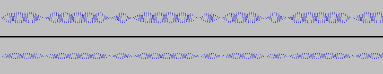
My first attempt at a filter was to apply it at each symbol, even when there was no change in phase. I quickly realized that this was incorrect and the filter should only be applied when there is a change in phase.
Ignoring the overall amplitude, the important part is that the waveform on top only applies it's filter before and after a phase shift.
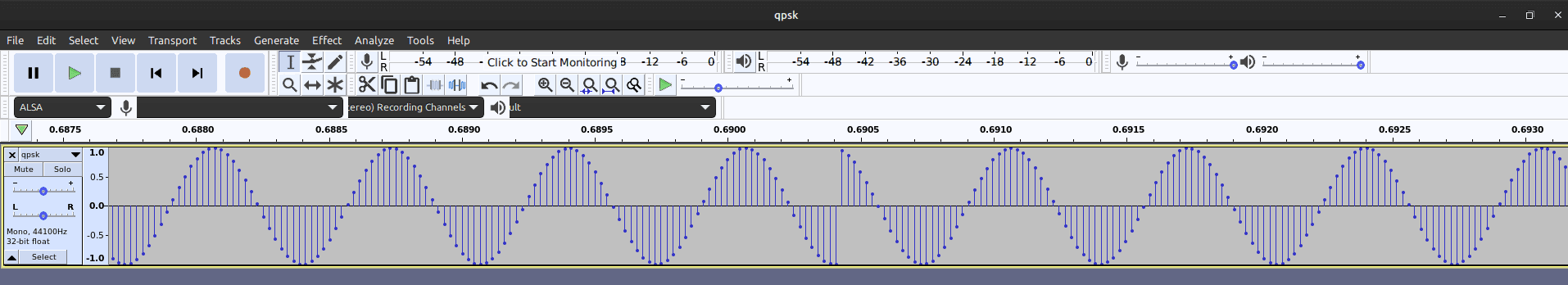
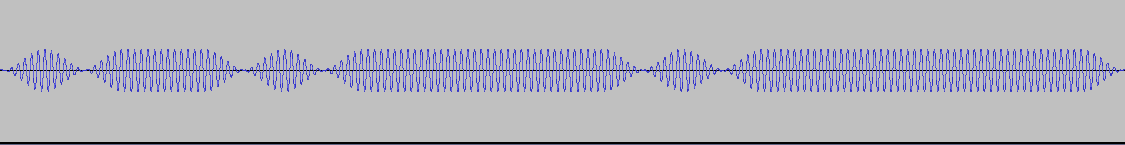
For some visual examples, this is what the filter should look like for BPSK during the preamble; the preamble is an alternating phase.
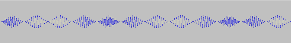
And this is what it will look like during the data portion where the phase will both be constant and alternating.
Here is what the audio sounds like with the filter: filtered.wav
Implementation
You can find all of my code here
For my implementation, I did not use any libraries as I encoded the audio directly into a .wav file. This was just a modified version of my simple wav file generator.
To start, I created a wav file and wrote the header, from here it's all about writing the data. As PSK31 is strictly text the only input that is needed is a string to encode.
With a lookup table for varicode, I was able to quickly convert the string into a continuous stream of bits. My buffer was a vector of 32-bit integers. I created a few functions that made it easy to write the data to the buffer so it would feel like a continuous stream.
With these things set up, preparing the bit stream was simple.
- Add the preamble
- Encode each character into varicode with 00s between each character
- Add the postamble
From here we can encode the varicode bit stream into audio!
The way that I did this was with a function that would encode one symbol at a time, taking in the shift and 'filter_end' as parameters.
Filter end is a boolean that determines if the filter should be applied, this is done when the next symbol is expected to have a phase shift.
This implementation is not efficient, but it is easier to understand, at least for me.
void PSK::addSymbol(double shift, int filter_end) {
    const double power = 2.0;
    const double roll_off = 2.9;
    const double amplitude = .5;

    double time = 0 - (samples_per_symbol_ / 2);
    for (int i = 0; i < samples_per_symbol_; i++) {
        double unfiltered = std::cos(carrier_wave_angle_ + shift);
        double filter = std::pow(std::cos( (abs(time) / samples_per_symbol_) * roll_off ), power);
        if (!last_symbol_end_filtered_ && (time < 0)) {
            filter = 1;
        }
        if (!filter_end && (time > 0)) { // Remove filter from end of symbol
            filter = 1;
        }
        int sample = amplitude * filter * unfiltered * max_amplitude_;
        carrier_wave_angle_ += angle_delta_;
        time += 1;
        if (carrier_wave_angle_ > 2 * M_PI) {
            carrier_wave_angle_ -= 2 * M_PI;
        }
        writeBytes(sample, 2); // write sample to wav file
    }
    last_symbol_end_filtered_ = filter_end;
}
| Variable | Description |
|---|---|
| power | The power to raise the filter to (raised cosine filter) |
| roll_off | The roll-off of the filter |
| amplitude | The amplitude of the signal, 0.0 - 1.0 |
| time | A counter that keeps track of the progress through the symbol, used to apply the filter (-samplesper_symbol / 2) to (samplesper_symbol / 2) |
| unfiltered | The unfiltered signal, just a cosine wave (y value) |
| filter | The filter, a raised cosine filter, so a value between 0.0 and 1.0 to multiply the unfiltered signal by |
| sample | The actual y value of the signal at a given x value. This is where the filter is applied. |
carrier_wave_angle_is a data member that keeps track of the current angle of the carrier wave.angle_delta_is the change in angle per sample, this is calculated from the frequency of the carrier wave and the sample rate of the wav file.max_amplitude_is the maximum amplitude of the wav file, this is 2^16 / 2 - 1 for a 16-bit wav file.last_symbol_end_filtered_is a data member that keeps track of if the last symbol ended with the filter applied. This is used to make sure that the filter is applied at the start of the next symbol.writeBytes(sample, bytes)is a function that writes a given number of bytes to the wav file.
It's certainly not a beautiful implementation as some of the raw math allows for a lot of this to be simplified, but the point of this is to show how PSK works even without understanding the complex math that goes behind hardware implementations of PSK.
Results
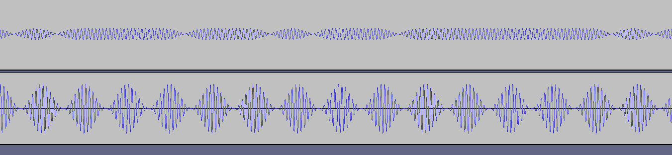
After playing with various filter values, I was able to get a great result. This is what my audio looked like compared to a sample from the signal identification wiki.
It was functional for all baud rates that fldigi supports but would get a little distorted at the higher baud rates.
Here is a video that shows the audio being decoded by fldigi at BPSK1000. I piped the output of man signalstack into the program just so I had a chunky bit of text to encode.
To test this I simply put the microphone from my headset close to the speaker.
Overall, the audio (below 500 baud) is encoded per the ARRL spec and looking at it in an audio waterfall it does not have any artifacts that I could detect.
The most interesting part:
At rates from PSK500 and below I was able to decode the audio without my microphone even being attached to my computer. My headphones share the same line as my microphone and depending on the level of the analog volume slider I was able to decode the audio without even being able to hear and without the mic being attached. This only worked when my microphone gain was turned all the way up in software, but it shows that the audio is good enough to be decoded through just EMI. This isn't anything new, as the NSA and NATO have been dealing with this since WWII.
Conclusion
This was a fun project for me, it was a challenge and it took multiple attempts to get it working. It's not a beautiful implementation of PSK but at baud rates bellow 500 it produces audio almost indistinguishable from fldigi and other PSK samples.
Sources
- https://en.wikipedia.org/wiki/Phase-shift_keying
- http://www.arrl.org/psk31-spec
- http://aintel.bi.ehu.es/psk31.html
- https://www.youtube.com/watch?v=Qe8NQx4ibE8
- https://en.wikipedia.org/wiki/Varicode
- https://www.geeksforgeeks.org/properties-of-waves/
- http://drmoazzam.com/matlab-code-bpsk-modulation-and-demodulation-with-explanation
- https://en.wikipedia.org/wiki/Tempest_(codename)